Friday 17 December 2010

Transforming (Converting) drawing co-ordinates from one system to another in Civil3d

For this procedure you need to work with two drawings one with the desired co-ordinate system and the other with the coordinate system to be changed. To my knowledge you cannot change the co ordinate system in one drawing at the click of a button to another coordinate system and transform the objects in that drawing to the new coordinate system at the same time. You always have to work with two drawings and pull/copy the drawing data from one drawing to the other transforming the data on the way.The quickest way I have found to do this to date is
1. Open a new (or existing) that is to have the correct co-ordinate system that you want. Check this drawing as the right co-ordinate system assigned to it by going to Toolspace->Settings Tab->Right click on the drawing name and choosing drawing settings->units.
2. Open the drawing you have that is in the would co-ordinates and check the co-ordinate system assigned to it as above if non is assigned, assign the correct system.
3. Open map workspace by typing “mapwspace” at the command line.
4. Attach the drawing you want to pull/copy the data out of by dragging it from explorer to the map explorer tab.
5. Write a query to pull the data in that you want.
6. Deattach the drawing

Wednesday 15 December 2010

Polyline Global Width

Reminder for me if someone has changed the global width in a drawing all the new plines will draw at that width set the PLINEWID variable to 0
to go back to a default width of 0.

How can you go 3D when you still get 2D

How many times have you wanted to use Civil3d and all its tools only to be served up some dxf or dwg thats 2D typically out of SDR Map, CivilCad or 12D with nothing but mtext heights and crosses. No blocks with attributes to extract the height data nothing.  Track down the original surveyor if still in business? Yeah right. Enter the points manually? No thanks.
Well maybe here is some code to help you get 80% of the way there in no time at all. Some of you may of seen it before as I originally posted it on the Autodesk Civil Community site a few years ago which has since been taken down. The code was pulled together from a couple of the VBA examples that shipped with Autocad and does not work with any Civil3d objects but could be extended to do the Civil3d point creation automatically.
Basically all you have do is :-
  1. Download the code https://sites.google.com/site/c3dxtreme/home/convert_text_to_point.zip?attredirects=0&d=1
  2. Figure out the typical x and y offset for the majority objects from the insertion point of the mtext containing the spot height text to the insertion point of the object marking the actual position of the spot height.
  3. Run the code.
  4. Enter the x and y offset.
  5. Enter the text used to represent the decimal character.
  6. Select the mtexts representing the heights and press enter.
  7. Bang Basic Autocad points at the correct height are entered at all the spot height insertion points.
  8. Use Civil3d built in tools to create Civil3d points, add them to your surface and we are in 3d and cooking with gas.
A couple of issues to note are if the survey is of reasonable complexity there will be a small percentage of points where the x and y offset has been changed most likely to stop text overlapping so manually drag the odd few points to the correct position once created with osnapz set to 1 so the z does not change. If a point can not be created as the text is something different the object colour is changed and you will have figure it out and enter it manually. Here is a demo video. 
Unable to display content. Adobe Flash is required.

Monday 13 December 2010

Pauanui Waterways and Marsden Cove Completion

Here are some photos of a couple of projects finished this time last year that were started way back in Civil3d 2006.


Added RSS Feed Button

Just added an RSS Feed button here is the link on how to do it.http://www.simplebloggertutorials.com/2010/05/how-to-add-subscribe-button-to-blogger.html

A little LSP selection Gem for Civil3d that keeps on giving

I wrote this little bit of lsp code way back in 2008 for the quick and easy selection of civil3d objects, before the “Select Similar” and “Select Object” functionality was introduced to Civil3d under right click on the shortcut menu in drawing space and prospector. 
However these commands have not made this code redundant, it just seems it keeps on giving time and sums up my core philosophy to using Autocad and Civil3d. If I can, I will find a quicker way.
Basically the code was born back in the day thru the frustration of having to use the “qselect” to find those pesky little diamond grading object markers in a drawing and the amount of time and clicks that it took to rebuild the same selectionset over and over again to find the little things and check if you were in the drawing or the grading in the drawing was corrupt.
Here are examples of the commands I use most frequently and how I use them in my workflow to save time.
  1. SelectGrading = SG , Type SG finds all the grading objects in a drawing. Right Click select Object View and there’s my model
  2. SelectFeaturelines = SF, Type SF and find and select all featurelines
  3. SelectAlignments =SA, Type SA select all alignments, Bring Alignments to the front, Make all Alignment Styles the same by pressing Ctrl+1 and changing the style in the property windows.
One advantage of this routine has over Select Similar is all similar Civil3d Objects in a drawing are selected even if the object styles are different. Unable to display content. Adobe Flash is required.
The code consists of 10 simple lines of code as follows:-
;************************************************************************************* ;this routine selects all the alignment objects is a drawing ;saves having to use the qselect command and clicking three or four times
(defun C:SELALIGNMENT () (ssget "_X" '((0 . "AECC_ALIGNMENT"))) (setq sset (ssget "P"))   (if sset     (progn       (sssetfirst sset sset)       ;(command "_.PROPERTIES")     )   ) ) (defun c:SA () (C:SELALIGNMENT))
;************************************************************************************** You can create more Civil3d and Autocad object selection commands by copying the block of code above and say if you were wanting to select Parcels select a parcel in a drawing and list it image  In the first line of the list you get the object type “AECC_PAREL” swap this for “AECC_ALIGNMENT” in the code block also change the SELALIGNMENT to say SELPARCEL and SA to SP. You can download the lsp file AH-Selectgrading.lsp I use here if you wish there are a few other routines included that you can delete out of the file if unwanted. https://sites.google.com/site/c3dxtreme/
If you guys like this sort of stuff leave I comment. If not tell me what you wish to know more about or what Civil3d should do you never know I may have been there and done it before.

Thursday 9 December 2010

What’s in a name of a blog

Believe it or not in coming up with a name for my blog I put a bit of thought into it. I finally came up with the Xtreme angle because now living in Queenstown it is extremely beautiful. There are loads of extreme sports you can do and with our great client we get to do some extreme projects. Like last week relocating and re building an old helicopter hangar for a new community market called Remarkables Market with in a week.
http://www.facebook.com/home.php?sfrm=1#!/pages/Remarkables-Market/120141908049598
Here is a clip of the helicopter lift of half the roof.
Unable to display content. Adobe Flash is required.

Learn Acronyms and become a keyboard Wizard

There is nothing I hate more than the time wasted moving the mouse to click a button. So I am a great believe in the power of the keyboard. To harness this power I use a lot of 1 to 3 letter acronym’s to trigger commands. I remember these by quoting the command to myself each time trigger it and having the acronym made up of the first letter in each word that makes up the command name so for example the command QuickEditFeatureElevs would be QFE. There are a number
of possible combinations using the 26 letters in the alphabet there are in fact:-
clip_image002 where clip_image004n = number of letters in the alphabet
k =length of the acronym
Number 1 Letter combinations
clip_image006
Number 2 Letter combinations
clip_image008
Number 3 Letter combinations
clip_image010
Therefore there’s 2951 lets say 3000 between friends 1 to 3 letter acronym’s that’s quite a few commands you can trigger from the keyboard. To add acronym’s commands you need to create a list of alias commands for the longer commands to do this :-
Open the acad.pgp file by selecting the following from the menus Tools->Customize->Edit Program Parameters(acad.pgp) or typing (startapp "notepad" (findfile "acad.pgp")) at the command line.
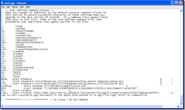
Scroll to the end of the file and add the user defined commands alias you want here is an example of the what is in my pgp file
image
Save and close the acad.pgp file and type reinit at the commandline and reload the .pgp file. Your alias acronym’s will be available.

Wednesday 8 December 2010

AUv Feedback

Well a couple of weeks ago I had a go at Autodesk University Virtual for the first time. I am afraid to say that it was a bit of a disaster in the factor that I only managed to catch one virtual presentation. I guess the feedback I have for the powers at be is :-
1. Not everyone lives in the US and therefore the figuring out of the timing of classes in you local time zone is a mission. The virtual site needs an Gadget that detects your local time zones and does the conversion of the times of classes automatically for you. (I did like the count down for the workshops then at least I knew how long I had to wait for something to start).
2. The browsing of virtual classes was also poor who scrolls side ways. The lack of a search function for class numbers to quickly add classes you wanted to watch to your tracks was a pain.  Therefore it was time consuming to hunt down the classes you wanted.

3. The changing of class times at the last minute meant I missed a couple of classes.
4.  Downloading of the outlook calendar appointments did not work for me as I am running 2003 at work I presume. I would of been interested to know if outlook would of done the time conversion for me. Also not everyone runs outlook therefore a function on the virtual webpage would probably be better foe everyone.

Cool new Assembly Tool

Automatically Label those Road Assemblies quickly

I am a great believer in the 80/20 rule and Civil3d seems to follow this to a tee. For example 80% of civil3d objects have a labelling style and 20% of them do not. One example of those objects that do not are assemblies and sub assemblies. Anyone that works with Civil3d on a daily basis will know the hassle when  you take over someone’s corridor model and have to figure out what assemblies are what. Tony on his blog tonyscivil3dworld gave a great tip at the beginning of the year of how to label assemblies with mtexts with fields.
http://tonyscivil3dworld.blogspot.com/2010/01/assemblies-names-labels.html

As I am what one could call a lazy drafter and do not like to sit there doing time consuming labelling. I searched the web for now one could add the labels to assemblies automatically and sure enough on Kean Walmsley’s blog http://through-the-interface.typepad.com he gives and example on now to add labels with .net http://through-the-interface.typepad.com/through_the_interface/fields/ so I have combined the two tips together in the following vba code for 2010 to do the labelling automatically. Here is a link to download the vba code
https://sites.google.com/site/c3dxtreme/home
and here is quick video demonstrating of what the code does
Unable to display content. Adobe Flash is required.
and here is a link on how to embed a video with jing http://www.techsmith.com/learn/jing/tutorials/share/embed-jing-content/ for those that are interested.

Saturday 4 December 2010

Drawing Cleanup and Standards

For those that have little experience with autocads built in standard controls check out Helen’s blog for cleanup and standards tips
http://helengorina.com/category/autocad/cleanup/

The Standards Police for civil 3-D Standards and Layers

Before you start getting into civil3d you really have to have your layer standards under control. All users or companies have some sort of default standard if only really basic. If you have no standards I suggest you create two sets of standards one
company standards and layers.dws (used for non-civil 3-D drawing)
This file contains the basic companies layers that have been traditional used and another the.
company civil 3-D layers.dws (used for civil 3-D drawings)
This file should contain the layers that follow the AIA layer naming convention as shipped from autodesk adjusted to have your correct company colour and line types for each layer.
Store the files on the network at the read only location such as "F:\Civil3d\Template\Drawing Standards"
Now you can assist drawing standards to a drawing by typing "standards" at the command line and browsing to each file and adding each file.
By default the standards files should be attached to the company template files and then will be present automatically when you create a new drawing based on company standard template .dwt. Some custom code can be written to check each drawing that is opened to see if the correct standard files are attached to catch those who buck the system or update old drawings to have standard files attached.
By having standards files attached to a drawing and setting the "StandardsViolation" system variable = 1 the user will be asked to pick a layer/textstyles from a standards file when they create a non standard object. To ensure that this variable is always set to one have the setting of this variable added to the acad.lsp file so on startup it is set automatically.
Note: On creating a new non standard layer an error window will now be displayed if the layer does not exist in the standards files the error message does not display until you press enter after typing in the name of the new layer when creating the layer in the layer manager. But by typing -la new and the new layer name at the command line the violation warning pops up straight away.
By having this variable set if you drag a style in civil 3-D from one drawing to another and the styles contains non-standard layers you will be asked to update them to standard layers.
Now you can import non civil3d standard layers into a civil 3-D drawing and as we have keep the shipped AIA layer naming convention in the civil3d file you can separate them out with filters if need be.
To filter layers to give everything but AIA civil3d layers that start with c- and v- typically create a layer filter with the following text
[~C-,V-]*
and you will be left with your old company layers or any layers that have been imported into the drawing that do not match the shipped AIA standards shipped with Civil3d.

Managing Civil3d Styles

Since I started used Civil3d back in 2007 the styles management and updating of your main template as you evolve styles on the job has been a completely inefficient process with the lack of built in tools. I have wrote my own vba code in the past to use the api to automate the process but have given it away now having found quux softwares tools in sincpac http://www.quuxsoft.com/. Check them out you get a free trail of all tools in the pac for 28 days and at $150 per module thats very cost effective. Compared to updating and writing  you own code or just wasting time drag and dropping styles.
Related Posts Plugin for WordPress, Blogger...