Sunday 26 June 2011

Mline Command

Going through some old cad manuals the other day came across the mline command I had never heard of that lets you draw multiple lines at once

http://www.dailyautocad.com/2007/08/multiline-1.html

Today I used it as I wanted too have a fence setback 6m from the top of a bank so set my mline scale to 6 to have the two lines 6m apart and started drawing

grip edited moving both line where needed and when finished I exploded the mline when into two lines and deleted the unwanted one.

image

Thursday 23 June 2011

Another Grading Paper

Just read John Mayo’s AU 2010 paper on “Featureline Grading for small projects”
http://au.autodesk.com/?nd=class&session_id=6948
covers alot of good grading tips as per my earlier post on grading. Check it out if you are into grading.

Wednesday 22 June 2011

Backup and Recovery

Sometimes even the autocad backups cannot help you. We use Shadowprotect to do 15min backups during the days saved my bacon a number of times with deadlines due. Grading ARRRRR!!!!! 

http://www.shadowprotect.com/

Tuesday 14 June 2011

Super UrbanSideWalk Assembly

As demonstrated at the recent New Zealand AU by Bryce from KarelCad you can use the Assembly Composer recently provided on the Autodesk labs site to create a Super Urban SideWalk assembly.
The need for this assembly in practice came about for a number of reasons.
  1. For GPS excavation the existing assembly does not allow for a true excavation datum surface from bottom links allowing for topsoil depth
  2. Sometimes you want varying slopes on the inside berm, footpath and outside berm
  3. Normally you want to strip all the topsoil from the berm and replace it with a specified depth of Topsoil
  4. To get accurate volumes for sidewalk construction you need a few more pieces of information than the shipped assembly provides
  5. You want to allow for the topsoil on any batters by attaching two daylights one for the finished top surface and the other for the datum excavation surface
This is what Bryce came up with.
image
Currently this assembly is a work in progress with trail technology so I will hold off unloading for you to download now.
Instead I will show you now to get a true datum excavation surface the old fashioned way. As shown in the previous couple of posts you can get a datum surface from your corridor reasonably easily. image However typically during excavation you would not leave the inside berm in place as shown as it is just not practical.
To remove it from your model
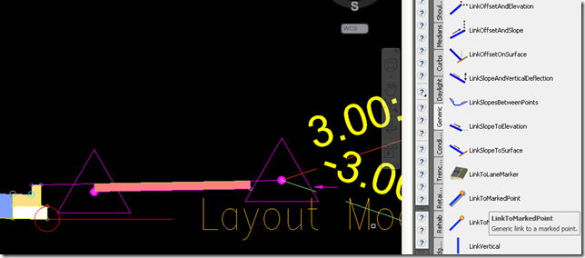
  • Place a marker point at the base of the footpath.
image
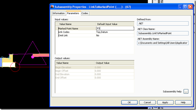
  • Give the marker point a name like P3,  by select right click the marker, going to properties, Parameters, Point Name
image
  • Insert a LinkToMarkedPoint connected to the back of the curbs basecourse
image
  • Select the LinkToMarkPoint, right click and go into subassembly properties and set the target point to P3 as created above
    image
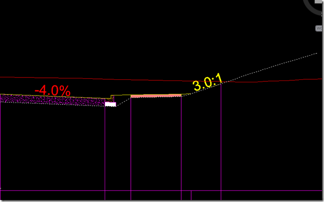
  • Rebuild your corridor and look at the section it should have the inside berm trimmed off.
image
You may also like to do the same for the outside berm and tie it into the toe of the daylight subassembly as shown in the picture above.

Monday 13 June 2011

True Corridor Datum surface for GPS excavation

When you create a datum surface for GPS excavation remember to set the “Overhang correction” on the corridor to “Bottom Links”
other wise the datum surface will jump up to any link on the top surface of an assembly that has a datum code assigned to it. Thanks Matt Kolberg for this tip

image


image


image

Selecting Corridor Region Assemblies and Zooming to

Not sure of the correct way you are suppose to jump to an assembly from a corridor to edit it but this is what I have been doing lately

  1. Have your toolspace open at assemblies
  2. Select your corridor
  3. Pick Edit Targets from the ribbon
  4. Hover over the region with the assembly of interest
  5. Note the name of the assembly in the tooltip
    image
  6. Go to the assemble name in toolspace
  7. Select and right click it and choose “zoom to”
    image
  8. Note too self there must be a faster way. Anyone?

Turning off Corridor Region Lines

Not sure why the region lines were appearing in my plan presentation style maybe a 2008 to 2011 thing

image

After hunting for a while found them in the corridor style. So I turned them off there.

image

Sunday 12 June 2011

Cleaning up Curb Triangulation with Corridor Breaklines

Sometimes your Curbs (or Kerbs) and Channels to do not triangulate well on a surface built from a corridor.
To clean up the kerbs you have to add the key Curb featurelines as breaklines to your corridor surface.
image
To do this goto the corridor surfaces tab and select the featurelines you want to add a breaklines
image

Monday 6 June 2011

Masking Civil3d Surfaces

As I mentioned a couple of weeks ago in my post on grading I like to use the elevations of the surface display style with a 255,255,255 pure
white background color to hide the contours of the existing ground surface under the proposed ground surface. This cleans up the drawing and lets you have colored
contours in the area of the proposed work only.
image
On a recent job however I was required to mask out half of the proposed contours
for a road. I run into a couple of issues the surface mask object did not trim the elevation triangles  i was using as hatching accurately to the road centreline. So i thought I could use the
“convertlineworktomaskblock” command and mask out the area of the surface this had an issue in that it did not mask the surface object contours. So I ended up using both features to mask the same area I got there but still
had to turn off the surface border to remove it from the drawing not ideal but just another Civil3d workaround that gets you there.
Related Posts Plugin for WordPress, Blogger...